
GymMaster Gym Software Manual
Doors and Readers
GymMaster software combined with door access hardware form an access control system which allows automated individualized entry
- Hardware
- Gatekeepers: Gatekeeper H6 · Gatekeeper H5 · Gatekeeper H4 · Gatekeeper Mini 4 · Gatekeeper Mini 3
- Door readers: Sentinel Wall Reader · Sentinel Keypad · Cidron · CN485 · CV485
- Desktop readers: Desktop Reader · Sentinel Desktop
- Other: Tailgating cameras · Key Fobs
- Installation and Documents
- Integrate Hardware with GymMaster
- Manage Doors
- Door Access
- Troubleshooting
- Frequently Asked Questions
Gatekeeper H4
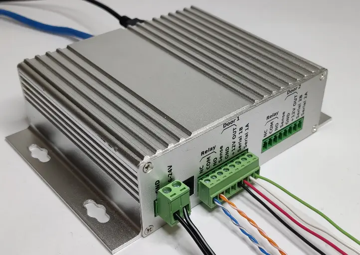
The Gatekeeper H4 is the access control processing unit for the GymMaster access system.
A qualified installer must install the Gatekeeper.
Install it in a location where staff can easily get access to it.
How it works
What it does
The Gatekeeper controls the entry and exit of people through the doors of a building. It is integrated with the GymMaster gym management software.
The Gatekeeper connects to these items:
- Two door readers, one for each door.
- Two relays, one for each door reader. The relays release the door locks.
- A maximum of four desktop readers, through the USB ports.
- Receipt printers and cash drawers (via kicker) through the USB ports.
A member holds an RFID fob near a door reader. The reader sends the fob details to the Gatekeeper. If the RFID fob is valid in GymMaster, the relay operates and the door lock releases. The reader LED changes from green to red, and the Relay LED on the Gatekeeper comes on.
The Gatekeeper H4 has no screen. A row of status LEDs shows the status of the Gatekeeper.
The Gatekeeper must have power and a connection to the internet. It sends the status of the doors to the server approximately each minute. If the server gets no status for more than 5 minutes, the Visitors page shows the Gatekeeper as offline.
The Gatekeeper must have these three things:
- A connection to GymMaster.
- A connection to the Internet, through the RJ45 (LAN) port.
- A link to a door reader in the GymMaster database.
After you install and test the Gatekeeper, register it at gymmaster.com/registergk.
To register the Gatekeeper Mini, use the MAC address on the sticker on the Gatekeeper H4. If this is missing, contact GymMaster to get your device MAC address.
Parts and connections
| Side | Connector | Use |
|---|---|---|
| Front | Status LEDs | The status of the Gatekeeper |
| Front | USB ports | Desktop readers and receipt printers |
| Front | Ethernet port (orange and green LEDs) | Ethernet cable to a router or a network switch |
| Rear | Power | Gatekeeper power supply (12V DC, 1000mA minimum), 5.5 mm x 2.1 mm barrel connector or 5.08 mm pitch Phoenix connector. |
| Rear | Door 1 and Door 2 (NC, Com, NO, Sensor, GND, +12V OUT, Serial B, Serial A) | Door lock relay, exit button and door reader, one connector for each door |
- Cash drawer: Usually, connect the cash drawer with an RJ11 cable to the receipt printer, not to the Gatekeeper. If you have no applicable receipt printer, use a USB cash drawer kicker. For a cash drawer with only an RS232 connector, use a serial-to-USB adapter, and speak to our team at GymMaster.
Door reader wires:
| Reader terminal | Gatekeeper terminal | Default Wire colour in the guide |
|---|---|---|
| GND | GND | Black |
| Pwr (12V) | +12V OUT | Red |
| A | Serial A (Serial 1A or 2A) | Green |
| B | Serial B (Serial 1B or 2B) | White |
Make sure that the colours agree with the label on the back of the reader. Connect the push to exit button to the same reader port.
Relays:
Each door relay is a Panasonic JW1FSN-DC12V. The Gatekeeper energizes the relay coil when a member has access. Then the relay changes over with a click: Com disconnects from NC and connects to NO.
| Item | Value |
|---|---|
| Relay | Panasonic JW1FSN-DC12V (high capacity type, sealed) |
| Contacts | 1 Form C (changeover): NC, Com, NO |
| Coil | 12V DC, 44 mA, 530 mW |
| Contact rating (resistive load) | 10A 30V DC |
| Operate time / release time | 15 ms maximum / 5 ms maximum |
| Mechanical life | 5,000,000 operations minimum |
| Electrical life, NO contact (resistive load) | 100,000 operations minimum at 10A 30V DC |
| Electrical life, NC contact (resistive load) | 10,000 operations minimum at 10A 30V DC. 100,000 operations minimum at 5A 30V DC |
Caution: Do not connect more than 2A to the relay terminals. The relay data sheet gives 10A, but the Gatekeeper H4 instructions give 2A maximum. For larger loads, install a secondary relay between the Gatekeeper and the lock. Do not connect mains (AC) power to the relay terminals.
The ratings are for resistive loads. Door locks are coils, so the relay contacts can wear more quickly. The IN4001 diode at the lock helps to protect the relay contacts. A fail-safe lock uses the NC contact. The NC contact has a shorter life at high current.
These values are from the Panasonic JW relays data sheet (ASCTB190E).
Door lock:
Caution: Do not use the Gatekeeper power supply to power a door lock. Install the diode with the correct polarity. Incorrect polarity causes a short circuit.
- Connect the door lock to the relay terminals (NC, Com, NO) of the door connector.
- Install a diode (for example IN4001) to prevent voltage spikes from the lock.
- The lock must have its own power supply.
- For loads of more than 2A, install a secondary relay between the Gatekeeper and the lock.
- Install an emergency fire exit button for safety, and to agree with local legal requirements. We also recommend an exit button.
| Lock type | How the lock operates | Relay terminals |
|---|---|---|
| Fail safe | The door stays unlocked when the power stops. | See the wiring diagrams in the Gatekeeper H4 instructions. |
| Fail secure | The door locks when the power stops. | See the wiring diagrams in the Gatekeeper H4 instructions. |
Warning: If you use fail-secure locks, have another way to unlock the door by hand. Then you can open the door if the Gatekeeper stops, for example if it has no power or no internet connection for a long period.
Network connection:
The Gatekeeper must have a connection to the internet. Connect it to a router or a network switch with an Ethernet cable.
| Requirement | Value |
|---|---|
| Connection | Wired Ethernet, Cat5 or Cat6 cable |
| Outgoing ports (open in the firewall) | 22 (SSH), 80 (HTTP), 443 (HTTPS) |
| Outgoing ping | ICMP |
Note: If a firewall blocks these ports, the Gatekeeper cannot connect to GymMaster. If an IT team manages your network, ask them to allow (whitelist) the Gatekeeper.
To find a firewall problem, switch off the firewalls in the network for a short test. If the Gatekeeper then operates correctly, a firewall blocks it.
Cables:
- Door readers: 4-core cable, 18-20 AWG (for longer runs) or a Cat5/6
- Network: Cat5/6 Ethernet cable.
- USB: 3 m (10 feet) maximum.
Power:
- Use the power supply that GymMaster supplies (12V, 2A).
- Otherwise, we recommend an Uninterruptible Power Supply (UPS) or battery with 12V output. Then the system continues to operate when the mains power stops.
Lights, sounds and screen
The Gatekeeper H4 has no screen. It has a row of status LEDs.
| Indicator | Meaning |
|---|---|
| Power on | The Gatekeeper has power. |
| Act1 / Act2 (or Ser1 / Ser2) flashes | The Gatekeeper can communicate with the door readers. |
| Reader 1 / Reader 2 on (green) | The Gatekeeper can see the door reader. |
| Reader 1 / Reader 2 off | The Gatekeeper cannot see the door reader. Examine the wiring, the cable and the reader. |
| Internet on (green) | The Gatekeeper has an internet connection. |
| Database on | The Gatekeeper has a connection to the GymMaster cloud server. |
| All OK on | All functions operate correctly. |
| Error on (red) | There is an error. For example, a door reader or desktop reader that GymMaster expects is not connected. |
| Relay on | The relay is opens. |
| Ethernet LEDs (orange and green) on | There is a network connection. Both LEDs must be on. |
| Relay click | The relay is engaged/disengaged. |
| Red LED on the power supply | The power supply operates. If this LED goes off when you connect the Gatekeeper, there is an electrical fault. |
Specifications
| Item | Value |
|---|---|
| Power requirements | 12V DC, 1000mA minimum |
| Doors | 2 (one 8-terminal connector for each door) |
| Relays | 2 (NC, Com, NO). Panasonic JW1FSN-DC12V relays (1 Form C) |
| Relay load | 2A maximum. For larger loads, use a secondary relay. |
| Network | Ethernet. Outgoing Ping, and ports 22, 80 and 443. |
| Screen | None (status LEDs) |
There is no data sheet for the Gatekeeper H4. These values are from the Gatekeeper H4 instructions. The relay part number is from GymMaster.
Related Documents
- Gatekeeper H4 instructions, h4.1 (PDF)
- Reader troubleshooting guidelines (PDF)
- Register your Gatekeeper (PDF)
- Replacing your SD card (PDF)
- Hardware documents
Next - Gatekeeper Mini 4

 2026 © Treshna Enterprises Ltd.